Sorted by Squirrels.

Friday 20 November 2009

I didn't want to leave.

I visited an amazing shop a while ago. I wanted an oscilloscope and the local supermarket was right out, apparently, so a quick search on teh interwebs and this goldmine was revealed...


There was more around the corner and behind the outcrop on the right. And even then all stock wasn't accounted for. Despite this the owner knew every item intimately. Well, not in the biblical sense. Ahem.
This is what I went home with:


The top one - a Tektronix 465B. Yes, of course I wanted it *all*, but, you know, space. The prices were stupendous and it was obvious that the owner was a real true equipment geek. There were instruments in the rear recesses of the shop which were straight out of a gothic horror - brass spheres held aloft a glass tube encased in a brass and rosewood cabinet - an actual piece of test equipment used for measuring kilovolts on overhead wires. Huge knife bladed switches and variable resistors where the resistance was set by inserting plugs at intervals along parallel copper bars... And a pile of meters and programmers and signal generators and... what the... I have no idea what some of these things were.

And the smell... Divine.

Anyways. That was a while ago. I offered to advertise the establishment but the proprietor was busy enough without the additional traffic. But I'm sure that if you were within visiting distance of Reading, England and you asked...


Thursday 8 October 2009

PL8-2, R2D2's Dad.

My children used to refer to C3PO as R2D2's dad. Funny how those minds work, isn't it.

I used to think that real fun could never be anything other than corporeal.

That just goes to show. This is the most fun that I've had in a while :)


It's the V2 incarnation (can that be right? There's no meat here..!) of the PL8 MMC interface.

Here she is, in full component-side glory.


The TTL is a simple read/write decoder. The port onto which this fits provides rough address decoding. I wish it would shave. I hate the chafing.


But I do so love the wiring.

It's a PIC - one of those manly sorts with the parallel slave port. I know it's terribly incorrect to use the word slave - oops I used it again! sorry! but that's just what it is. So the parallel slave port behaves like a chunk of selection logic and wakes the PIC when a read or write occurs. There are /RD and /WR lines. The microcode on the PIC latches data ready to be presented on a port when the /RD line is asserted. No delay, it behaves just as a latch would. Similarly asserting the /WR line will latch the values present on the data bus to a register. Interrupts ensure that these events are recognisable and the remainder of the uC code is shuffling data to and fro.

The performance of this type of interface is already documented in another post <> milliseconds to load programs <> so I won't go into it here.

Needless to say schematics and code, both micro and 6502, are available if you'd like them.

Atom VRAM mod

I have really struggled with the question 'should I modify this rare vintage micro or leave it as-is?'

Well. The thing about the Atom was that it invited modification.

So I came.

To the party that is, the one that the Atom invited me to. Honestly. Some people.


This is the truncated version of the ill-conceived all-in-one memory board that I started some while ago. It's simply VRAM. Nice. Witness the burned-off resist at or about pin 15. Ahem. Ah well, it's all for the greater good. 2114s are not exactly super-rare, but they use so much wattage. It's not green, it really isn't.

Tuesday 6 October 2009

Retro Computer Museum Open Day 2009

The organisation most commonly known as The Retro Computer Museum are having another all-day gaming event. For those in the UK willing to travel to Leicester you should visit their site and get the low-down.

I'll be taking a boot load of kit to fiddle with over the course of the day and I might even indulge in a little gaming. I'm mad like that, me.

MMBeeb

Not a voluptuous expression of joy for a broadcaster, but one of these...


... being an MMBeeb board. I have mentioned them before, but I've improved the design somewhat since then. This is from the last batch. SMT components and a rather cheeky regulator placement make these the tiniest and most comely batch yet. I like to make each one different, unique. Electrically they're identical but each has its own character. I like to talk to them when I'm alone.


An MMBeeb board plugs into the user port of a BBC Micro and coupled with some smart coding by the original creator Martin Mather gives the contemporary BBC Micro user the ability to have at their disposal literally thousands of disk images all instantly selectable and appearing as though a genuine 5.25" disk.

They're fast too, programs load in seconds. G'orn there Chuckie Egg!

Monday 14 September 2009

Mending

Finally I've had some movement towards finishing a job. Really, it's been a long time :)

A poorly Atom belonging to a friend required a key switch fix. The keyboard on Atom motherboards of issues 1..4 is a strange all-in-one affair where the switch mechanism is a pair of counter-wound springs which connect when a weedy plastic plunger depresses them. They are puny and prone to breaking.

The only effective fix is to cut out the broken part and insert a new switch, as I believe I have blogged about before. This would be a new challenge as the switches I replaced before were at the end of a row and were changed as a unit. This time I would attempt a single unit as I have run out of replacement parts to do the two adjacent switches...


This is the first time I've used my callipers and I must say they're jolly useful.


Here's the replacement switch ready to be dropped in. The antennae were added so that the tiny whisker-like wires at the base of the switch would register correctly with the holes on the PCB. The replacement part is ever-so-teensily different from the one it's replacing, so registration wasn't guaranteed when sliding the piece into the anxiously awaiting gap. When the sides of the switch were coated with superglue that would have been a problem. The extensions fell away as expected when the solder joints were applied.


Hurrah!

Tuesday 8 September 2009

Grzzzzzz!


With a Pic for a brain and a mouse for motion tracking you should consider your hiding options before the head-mounted laser gets added. You have been warned!


Tuesday 23 June 2009

Learning as you go

FAIL!

The board was a brave attempt, but I should have trusted my instincts which said 'This shouldn't work. There's strange voodoo happening.' Here's the inspiration:


The 8K video RAM replacement chip is wired such that /OE and /CE are both tied low. Aha, it's being controlled by CE2! Nope. That's tied high.

Here is the type of board that I was working from. You see on the left how pins 28 & 26, 22 & 20 are tied?


Hmm. It works because the address lines from the video RAM to the VDC are isolated from the rest of the system by some bus buffers. Unless the video RAM is being accessed by the processor it remains 'firewalled', with data presented to the bus constantly. This isn't a problem as the VDC only reads. Reads from the CPU side are also OK as the firewall is only opened as the CPU wants data on the bus. Accessing the video memory on the Atom produces snow. This will be why, then! The data in the memory location you're accessing is displayed by the VDC instead of the data at the current scan position. I'm still not 100% sure how this all works so I'll pore over the schematic with a nice cup of tea and a sticky coconut macaroon later.


The upshot of this is that any memory expected to live on the CPU side of the tracks cannot share address lines with the video RAM. You will not be able to access the memory as the firewall is only opened for addresses in the VDC range.

I'm strangely unperturbed by this failure. I expect it's because I know that electrically everything checks out. It's just the mechanical arrangement that's wrong.

Onward to plan 2!


Sunday 21 June 2009

Happy Father's Day!

The Atom needs some non-volatile random access storage. I ran out of suitable patience burning EPROMs when updating the firmware for the new MMC board. The old firmware was developed with the aid of an MMC simulation that I shoehorned into the MESS emulator. The simulator allowed me to code against a just-accurate-enough model of an MMC card in SPI mode. The new interface doesn't have such a luxury yet. So I got thinking, and decided that the 32kx8 FRAMs that I got from Ramtron recently would do as an EPROM replacement. But I'd still need the firmware in EPROM available to bootstrap from... Hmm. I'd also been meaning to build a copy of a neat videoram replacement card that I found in an Atom belonging to a friend. So that was that, really. Or rather, this is that:

At the moment it's only the video ram replacement side of the equation. The flying lead takes A10,11,12 from the main board. The rest of the signals are picked up from the vacated 2114 sockets. The empty socket is going to take the FRAM and some decoding logic will live adjacent, unless I can find suitable signals to pick up from the motherboard.

Not all underbellies are soft; This was quite hard, actually:


I shall return with news of FRAM. Dear, dear FRAM.


Thursday 18 June 2009

AtoMMC 2.0

What's going on here then?


Let's see ... that's:

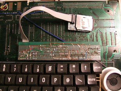
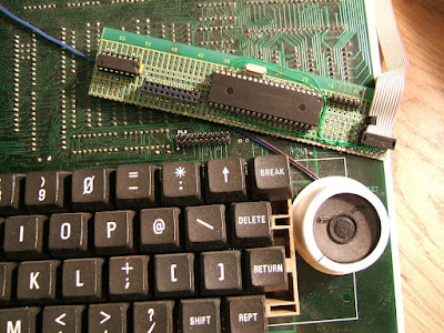
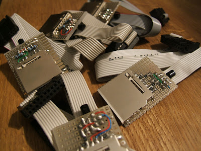
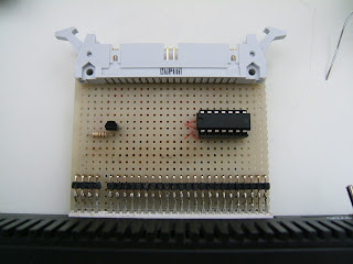
Acorn Atom Rev.4 with PL8 fitted +
Microchip PIC 16f77 +
74ls00 +
Custom firmware +
DScaler 4.1.15 +
Saleae Logic 1.0.21

An equation that = Joy.

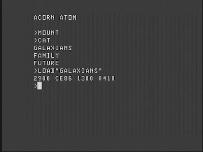
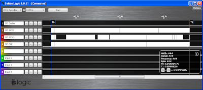
Here's the trace of SPI activity whilst loading the above program from MMC. Click for a larger view. Go on. I know you want to.


That'll be ~5k of Galaxians loading in ... ooh let me see now...


Oh yes. 0.3 seconds.

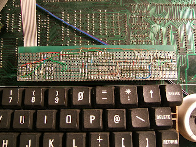
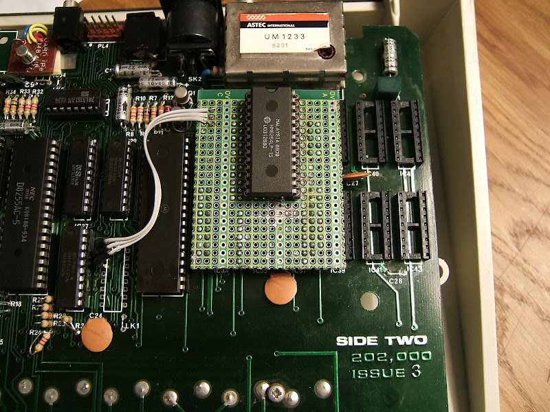
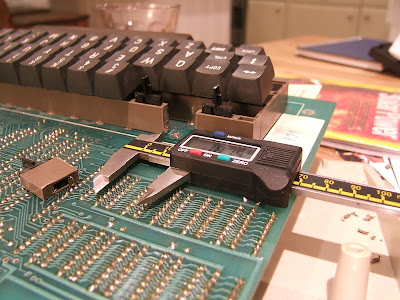
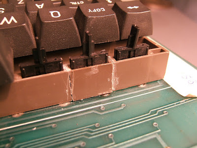
The previous board sat cuddled up to the VIA and all of the SPI communication was performed by banging bits against one another. This board takes bytes at a time, like a man. These are then passed on to the inboard SPI hardware and the reply posted back.

Some PICs, like the one used here, have what's called a parallel slave port. You access it like any other bus-based device. It has /EN, /OE and /WR lines which directly control the state of one of its 8-bit data ports. With no valid control signals present the chip sits happily processing with the PS port data lines in a high impedance state. Enabling the chip and clocking /WR will latch the data found on the port at that time. Similarly asserting /OE with the chip enabled will take the port out of high impedance state and present latched data to the bus. There are separate latches for reading and writing. The reception and recovery of data can cause an interrupt. Very handy. Having been an AVR freak for a long time now since migrating away from PICs I'm starting to see their appeal once more. There. Ah sayed it. I Love PICs. Again. I don't know why I fell out of love with them, I suppose it was becasue they felt rough and ready. AVRs were sexier. With better development tools. I digress.
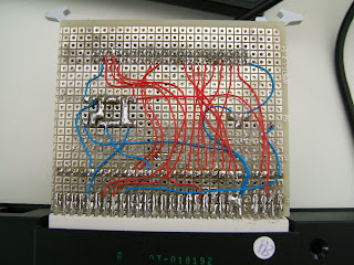
So with appropriate code written, and some neat decoding logic in place to translate the 6502's r/wr signal to separate /RD and /WR signals away we go. Fortunately I'm a reasonable programmer and the AtoMMC firmware that I wrote for the VIA interface was device independent. After as long as it took to recompile and burn a new EPROM, I had a new working driver for the new working hardware.

In all the round-trip time from presenting a byte to the chip to receiving a reply is as long as it takes to process the following 16 cycles:
;~~;~~;~~;~~;~~;~~;~~;~~;~~;~~;~~;~~;~~;~~;~~;~~;~~;~~;~~;~~;~~;~~;~~
;
; spi transfer
;
; on entry
; A = byte to transmit
;
; on exit
; A = received byte, Y preserved, X trashed
;
xferbyte:
sta $b400
nop
nop
nop
nop
lda $b400
rts


Quite a big difference from the original code..
;~~;~~;~~;~~;~~;~~;~~;~~;~~;~~;~~;~~;~~;~~;~~;~~;~~;~~;~~;~~;~~;~~;~~
;
; spi transfer
;
; on entry
; A = byte to transmit
;
; on exit
; A = received byte, Y preserved, X trashed
;
xferbyte:
stx XBTEMP
sty XBTEMP+1

ldy #8

xb_xferbit:
sta XBTEMP+2 ; ZP write .. faster than PHA

and #MOSI ; present data, CS is low
ora #CLK ; bring clock high
sta VIA

ldx VIA ; read data

eor #CLK ; bring clock low
sta VIA

txa ; rx'd data into carry
ror a

lda XBTEMP+2
rol a ; 7<-next bit, 0<-rx'd data

dey
bne xb_xferbit

ldy XBTEMP+1
ldx XBTEMP
rts

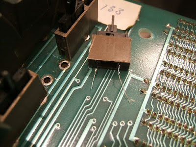
All this joy has happened relatively quickly since receiving my logic analyser. I don't know how I coped without it. Having a window onto the private world of your signals is more revealing than the televisual programme 'Katie and Peter'. Speaking of feeling dirty I must admit that I used to feel the idea of attaching a peripheral processor arguably more powerful than the host computer to be anathema. However now I'm over the initial revulsion I have to admit I quite like it. Again I digress. So for a perfect example of how having an analyser helps, let's look at the behaviour of the flip-flop that I programmed to change whenever a SPI transfer completes:


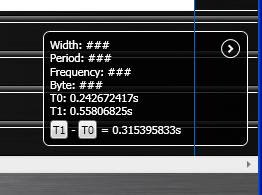
You might be able to see it in the thumbnail here, but click for more pixels. The top two signals are enable and write. Taking the falling edge of the write line, when data is latched from the bus and passed to the SPI hardware, we see that the third line, rdy, is flipped about 12 microseconds later indicating that data is ready for reading. The writes occur at about 16 microsecond intervals. Remember the 16 clock code earlier? Aah yes. That code was generating this trace. I could probably drop a couple of NOPs to push things a little faster but I want a small comfort zone. I could also use a faster SPI clock. I'll perhaps experiment with that another time.

Mmm. Katie and Peter. Dirty boy. Go to your basket.

Rapidly scribbled and then

Monday 8 June 2009

Brokenated XC-Special


Let's have a little look, shall we? You might feel a sharp scratch... Aah yes that'll be it, then.


I should really conjure up some more robust button scheme. The key switches give the buttons a better feel than the standard tact-switch. Fixing them however has been a case of applying epoxy until they no longer give way. Unfortunately plastic to metal isn't an optimum bond and this is the third time I've had to get the mending kit out. Here's an exploded view:


Here's where the magic happens:


I shall be playing a quick round of Sea Dragon when this glue has gorn orf.

Thank you Atari for deciding serial was the way. You too, Commodore. We can laugh about it now but at the time it was terrible..!

Sunday 7 June 2009

FTW!

A little vulgar I know, but it's an adequate expression of how I'm feeling right now.

The SD2IEC is working beautifully. Up to this point it was suffering from some syndrome resulting in erratic behaviour at best to a more normal position of outright refusal to work.

I could make things work sometimes by shimmying wires around, so this seemed to be the obvious first move. I stripped all the long wires away and remade the connections. It's often easier to see where a wire should be routed second time around...

While I was at it the ceramic resonator that I used originally was swapped out for a proper crystal. As I've got JiffyDOS in all my C= machines it is necessary to have an accurate clock source. Fastloaders demand cycle-accurate timing and both the internal RC oscillator and resonators are lacking in the accuracy department, to coin a contemporary phrase.

I reworked the cable too as the original one was made from some CAT5 (yellow, yum!) and had been shortened a couple of times to try and increase reliability. The resulting splices were ugly so had to go.

The result of all this industry? Bing bing bing bing Jackpot! Solid, speedy loading. C128, C64 and VC20 all enjoying the flowing bits.


The cassette case is a scaling back of the original scope. I was going to mount it inside a C2N datasette player, hence the fashioning of the board into a rough cassette tape shape. This was because my first SD floppy emulator was a SIO2SD board for 8-bit Ataris, built into the shell of an XC12 (Ugly, ugly brute) cassette player, which I may well present soon as I have to go back inside it to repair a keyswitch.

Here's the board, naked and from behind - exactly how I like it:


I am constantly in awe at the fine people who produce these fine projects. If I had to doff my hat every time the awe swelled within, I would be doffing almost continually. Lars P, Unseen and countless others, you know who you are, you have my deepest admiration.

The features of this device are too many to mention, who would have thought that an ATMega644p, some discrete components and a few hours soldering oculd have produced a wonderful thing like this?! I'm thinking that the SD/MMC bootloader might have to be employed in the Arduino board when I get a 328 to play with...

Considered,

Friday 5 June 2009

Thrice nay!

It's a nonsense title for a post, but I was just thinking of Frankie Howerd.

I have a shameful admission. I lied in my last post, or at least mislead you, dear reader. There were 5 projects - though I suppose the scale of this one didn't really register on the need to win scale.

I made a mega-rom adapter for my Atom. I haven't inserted a large image for a while (Matron!), so here goes:

The mega-rom! In an Atom! It allows me to page in one of 16 4k images into the address space allocated to utility software in the Atom's address map. The switch carried with dignity at the end of the cable allows a user to perform the magic. But you probably worked that out.

Don't you just love the green and yellow striped electrical tape? I was speaking to an electronics fashion pundit at the RCM event and they told me (in the strictest confidence) that this years projects simply must have green and yellow electrical tape! Being the capricious sort that I am I simply have to agree, at least for today.


I have been expanding my horizons, not to mention my old computers - ha ha, with contraptions such as this, fabricated with board spacers and socket strip. These nifty connectors are ideal for making up adapters like the one above.

Pictured: A board spacer is sized up by an interested socket strip

I've tried a number of different makes but these are by far the best - If I were Victor Kyam I'd buy the company. Which is SamTec if you're interested. No, I'm not receiving a back-hander. Though if you're reading, SamTec - well let's just say I'm interested... ;)

There is a slight wrinkle in the construction of these boards. The socket has to be mounted on the same side as the pads. I've yet to find a supplier of through-hole plated proto-board, but when I do I'll use it for this purpose. In the mean time, I use one of two methods. The first involves a 'cost efficient' socket - the pressed pin variety. Splay its legs akimbo and apply solder. Place it right-side-up on the padded side of the (woeful , now I think of it) protoboard that my local electronics supply chain provides. It rhymes with Craplin if you're wondering. Affix to the board with a swift application of iron. Bingo! The 2532 adapter for the tier jerker was manufactured using this method. Apply your eyes to the previous post for a fine example.

The second method, as used here, involves the socket strip. Place this adjacent to the spacer, at chip's width naturally, and solder the pad to the socket where it meets the board. You need a fine iron and a steady hand for this so no beer or porn beforehand. Ooh which reminds me... What?? Oh hush, I'm not soldering tonight.


Here you see socket strip and spacer conjoined with solder bridges. Which are surprisingly hard to make intentionally!

Lordy I've wittered on long enough. I have an SD2IEC to attend to. Please excuse me :¬)


A third-class ticket to despair and back

I couldn't make it work. I tried... Alas the Fail was strong in this one.

The spectrum wanted its CF adapter. I wanted to oblige. I tried a number of different cards which all appeared to be lacking in Win. I had checked over the wiring a number of times and, although not entirely convinced it would help, I thus set about rewiring the beast.

Guess what! Still no Win. The board resolutely refused to
play nicely and so I took a step back and considered all the possible failure points. Too much stray capacitance? A dry joint? Lack of understanding? The list goes on. At last I decided to cut my losses and re-work the board as an IDE interface. Several tens of minutes later, having used an entire roll of desoldering wick, the board was bare but for the edge connector.

It's a good job I only regularly watch one TV programme (The Apprentice, with S'ralan), as I could get on with some burning myself.

The result:


Joy! I'd carefully checked each connection as it was made and I was certain they were all good. I'm bouyed by the assurances of my meter, and sure of at last securing a payment of success to offset the miserable week spent futilely poking at the CF board. Apply power, insert device -

...

Misery.

With heavy heart I put this project aside until some future time when I can muster the strength of character to return to the joyless debugging. It didn't get much better than this for weeks. I've started four more projects since, each more resoundingly failful than the last!

So that, dear reader, is why there have been no updates. I'm afraid I don't have the strength of character to tell of my winless ways. I can't even bear to tell you what they are. I do intend to return, though, this time with bigger guns. More on that later.

What I needed was something simple to rejuvinate my mojo. To get me to the power-pill so I can start to chase those ghosts.

My opportunity came at a recent retro-computer themed event where I met up with a number of people thus far only identifiable by a 24x24 pixel avatar and psychologically revealing nickname. Amongst these a contact who keeps me fuelled with rare Acorn Atom goodies. In this case I was knighted with a home-built rom-box, containing a couple of eproms.

Forget the soviet nuclear-warhead launching switches! The mysterious dials and socketry - this is truly a thing of beauty. But like most beautiful things, it's what's inside that counts. And that was going to be ME. The dumping challenge was on! [If you or someone you know built this rom-box, then please get in touch!]

Once retrieved from the secure caress of their sockets the lovely ceramic packaged gold legged EPROMS were quivering in the palm of my hand like frightened baby Meerkats. These chips are ancient and JEDEC incompatible. 2532s. 32Kbit arranged as 4K x 8. Here is the adapter I built to allow me to read the eproms using the glorious tier jerker:


And in situ:


As it turned out they contained images of programmers' toolkits. I must admit I was hoping for a rare find, however the images in question are already well known. But that is by-the-by. The thing is an hour had been spent with a soldering iron, a further hour spent reconfiguring the client application to draw the data PC-ward by the magic of electon in serial cable, and then some moments of joy - as the contraption worked. Worked?? WORKED!

I believe my drought is ended. The rains of win are falling, filling drained butts of enthusiasm. I shall venture forth and tackle the next item - Upgrading my SD2IEC in order to take advantage of the JiffyDos-enabled commodore machines at my disposal...

Wednesday 4 March 2009

Why?

Why do I do this to myself?

I've been meaning to start on the ZX Spectrum Compact Flash project for a while now. This site has some great stuff. Pera Putnik is a bit of a star in my humble opinion.

First things first - the terror inducing removal of the incumbent spectrum ROM with a Dremel cut-off disk. No pictures of this process exist as it's so fraught that taking a snap is all but impossible even with the most advanced image stabilisation techniques. The process is thus: (I'm shaking jut thinking about writing it..)

Cut through legs at top of ROM with Dremel. Remove remainder of legs with iron, wick and sucker. Solder in socket. Insert ROM. Relax.


The wire here is A14, I've used a 32k EPROM with 2 images burned in; the regular ROM and PP's CF OS. There's a splendid video that shows the thing in action. I can swap between the 2 with a simple flick of a switch.

Pictured below is a SparkFun CF Breakout board connected to some protoboard with pin headers. The edge connector there is soldered on one side, and I made connections to the second, floating row of pins using some 90 degree header. Click the pictures for the full resolution horror.


This hangs off the back of the spectrum. Now all I have to do is wire it.


Blisters aside, it's getting harder to do stuff like this as my old eyes are gradually losing their ability to focus at close range. It was fun though. And I've had an idea about a soldering station with built-in magnifier...

Now all I have to do is get it to work!

...

Cult of Done

Pretending you know what you're doing is almost the same as knowing what you are doing, so just accept that you know what you're doing even if you don't and do it.

Read, Loved and

Wednesday 11 February 2009

MMmm.. Beeb!

I linked to the excellent MMBeeb project in an earlier post. It's been at the top of my project list again as I'm taking a pile of BBC B computers to TechAdventure which I'll be attending at the end of the month. I'm hoping to talk about MMC, old computers and the conjoining of the two. I'll have a table full of retro equipment to show, and some to sell.

As one of the first MMC projects I undertook, the MMBeeb board was a stepping stone that led much further than I expected. Whilst revisiting it in the light of all the knowledge I've acquired since then I've come to the conclusion that there are some subtle bugs with the original hardware. I'm hoping to contact the originator of the project and see what he thinks. I'll post an update here as soon as I've determined if I'm on the right path. In the mean time enjoy the view:


The revised circuit uses the same standard resistor divider as used on every other MMC interface I've ever made and a 3v3 regulator. That's it. It's not the hardware that makes MMBeeb special though - it's the software. It's a stupendously slick DFS conversion that integrates smoothly into a system. It also works with a second processor, which is an indication of the care and attention to detail that Martin has put into his work. And for the few paltry Great British Pounds that it costs for one of these you'd be crazy not to..!

Libraries

It's all go at the moment. Last weekend I attended my first DorkBot London meeting. I must confess I didn't really know what to expect but spent a very pleasant, if cold, day in the company of feverishly soldering artists and makers. I spoke to many people about uFat and the new DevicePrint library. This is some code that allows formatted textual output to a buffer in memory and thus onto some form of persistent storage...


You can get the new library here SMB_LIBRARIES. It adheres to the principles introduced in uFat:- it is lightweight and device agnostic. It should work with any storage medium as long as there is a function available to write a 512 byte sector.

The the code is initialised with a pointer to a buffer, some basic information about the destination sector area, and a writer function. From that point on you are free to use the familiar .print() functions which are best known in their Serial library incarnation. The Arduino base library provides you with so much more than a blinking LED ;)

As usual (1) - there is copious documentation in the form of comments and an example sketch configured to use MMC storage for you to play with. If you wanted to try it out without any devices available then you could always change the write proxy routine to dump the stored data to serial.

As usual (2) - comments welcome!

Toasted and

Friday 30 January 2009

Chrome Tips

Two chrome tips for you:

1. The Type 55 0.5mm tip for my new favourite tool-in-the-box - an Antex XS 25 watt soldering iron! Ahem, while not exactly chrome, it does go shiny when tinned! I've only ever used my old workhorse cheap-and-cheerful 50 watt iron before now, which as far as I was concerned was as good as it got. So I was dubious when I was given this little gem to try. Imagine my surprise when I saw the difference that this iron/tip combination makes. I must say I'm absolutely astounded. It manages to pump much more heat into a joint than my supposedly more powerful iron that joints form instantly and cleanly. I'll never use another iron again ...

2. If you're having trouble downloading updates to the ever-so-likeable Google Chrome browser due to proxy issues or similar, then try this. Locate the event viewer for your Windoes system. This is usually in the Administrative Tools section of your control panel. There may well be an entry from the update manager which looks like this (click for a full resolution image):


You will see the URL to which the update service is attempting a connection. Cut and paste this into your favourite browser's address bar. In my case the download hoops are presented and I can duly jump through them, ending up with a newly polished chrome tool. Matron!

Double entendre added then

Thursday 22 January 2009

Say Hello to uFat2

There has been a flurry of activity recently and a number of uFat users have been in touch, which is nice! In response to this I think it's about time that I posted my latest updates. The code is thoroughly commented and should answer most questions.

Most notably I have broken the dependency on a particular device library. Now you can use any code capable of reading 512byte sectors from any FAT formatted device.

Since a number of you dear readers asked about traversing FAT directories I've abstracted this requirement into a core feature. By providing a function callback you can now process FAT directory entries to your heart's desire!

It's still a lightweight library but there may be new ideas here for some beginner programmers. I don't think there's anything that should scare anyone though. Concepts such as pointers to functions and PROGMEM data storage are used throughout, but you should be able to use this as it stands without this knowledge. The example sketch should cover the most obvious use cases of printing a listing of files and updating a file on the card.

I developed this under the latest IDE at time of writing which is Arduino-0012. As usual, I'm happy to help with any problems or queries you might have.

Here's the goods: SMB_LIBRARIES and for pudding: The demo sketch

The code is now hosted on Google Code. You can download it here

Refer to the header files for usage, tips, and perhaps a LOL or two. If you're lucky ;)

Written, admired and duly

Contact Form

Name

Email *

Message *

This is how we do it

MMC (9) acorn atom (7) zx81 (7) sord m5 (6) arduino (5) multicart (5) Sord (4) tatung einstein (4) Atari 800 (3) Chuckie egg (3) M5 (3) M5Multi (3) c128 (3) sd card (3) sd2iec (3) sio2sd (3) 6502 (2) Max6956 (2) QL (2) RCM (2) assembler (2) avr (2) c64 (2) cadsoft eagle (2) eeprom (2) einSDein (2) mmbeeb (2) multi-cart (2) spi (2) system 80 (2) ufat2 (2) vic20 (2) video genie (2) 6502 second processor (1) 6522 (1) 8255 (1) Acorn BBC Micro (1) Apple 2e (1) Apple ][ 2 two (1) BBC 6502 second processor (1) BBC micro (1) DevicePrint (1) Double Choc Chip Muffins (1) FAT (1) IO (1) Jupiter Ace (1) LED (1) Master 128 (1) PCB (1) PIC (1) POV (1) PROGMEM (1) Pineapple (1) ST (1) Spectrum 128 (1) antex (1) arcade spinner (1) arduino shield (1) atari (1) atmel (1) bakewell tart (1) beer (1) bird's nest (1) bitbucket (1) brokenated XC special (1) cake (1) cassette (1) cassette interface (1) colecovision (1) compact flash (1) convert (1) dac (1) de-yellowing (1) dev cart (1) eaca (1) efficient (1) einsdein. z80 (1) esp32 (1) esp8266 (1) eye strain (1) failosophy (1) filesystem (1) finally (1) fram (1) french polishing (1) fuse (1) fuses (1) games (1) gaming (1) github (1) glue (1) google chrome (1) heroic failure (1) high voltage programming (1) hot irons (1) if (1) jiffydos (1) joey beltram (1) lego robot (1) library (1) lying (1) machine code (1) matron (1) microcode (1) mmc interface (1) mmc2iec (1) mmm (1) mouse guts (1) oscilloscopes (1) pcm (1) pic32mx (1) porn (1) proto shield (1) purple (1) repo (1) retro computer museum (1) retro hard-on (1) rom box (1) sd (1) sd-x (1) sd2mmc (1) seadragon (1) silliness (1) small (1) software master (1) soldering (1) spi software master (1) stray capacitance (1) string (1) techadventure (1) test equipment porn (1) ts1000 (1) turtle cheesecake (1) tweaking (1) vc20 (1) video head (1) video ram replacement (1) weewee (1) wingasm (1) wire library (1) wodges of IO (1) xilinx cpld (1) yellowing (1) z80 (1) zx spectrum (1) zxpander (1)
Unless otherwise stated all of the original work presented here is:

Creative Commons License
Licensed under a Creative Commons Attribution-Noncommercial 2.5 Generic License.

The work of others where referenced will be attributed appropriately. If I've failed to do this please let me know.